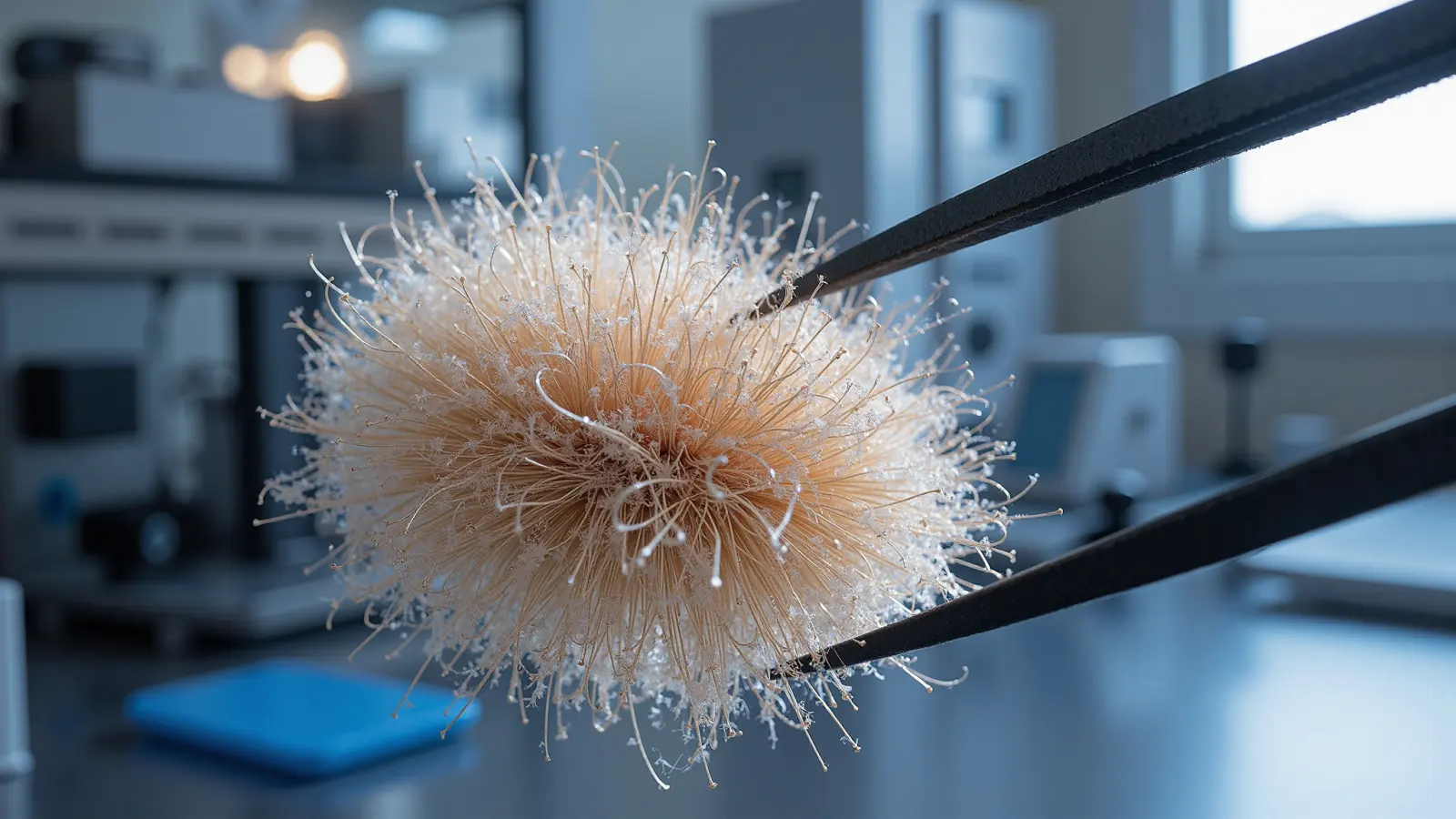
Why Fiber Optic Testing Matters
Fiber optic networks form the backbone of modern telecommunications, data centers, and enterprise infrastructure. Unlike copper cabling, optical fiber carries data as light pulses, demanding specialized testing procedures to verify signal integrity, attenuation levels, and overall link performance. Without rigorous quality assurance at every stage—installation, commissioning, and ongoing maintenance—networks risk degraded throughput, intermittent outages, and costly downtime.
This guide walks through the four essential testing methods every fiber optic technician and network engineer must master. Each step builds on the previous one, creating a comprehensive validation workflow that ensures your optical infrastructure meets industry standards such as TIA/EIA-568 and IEC 61280.
Step 1: Optical Time Domain Reflectometry (OTDR)
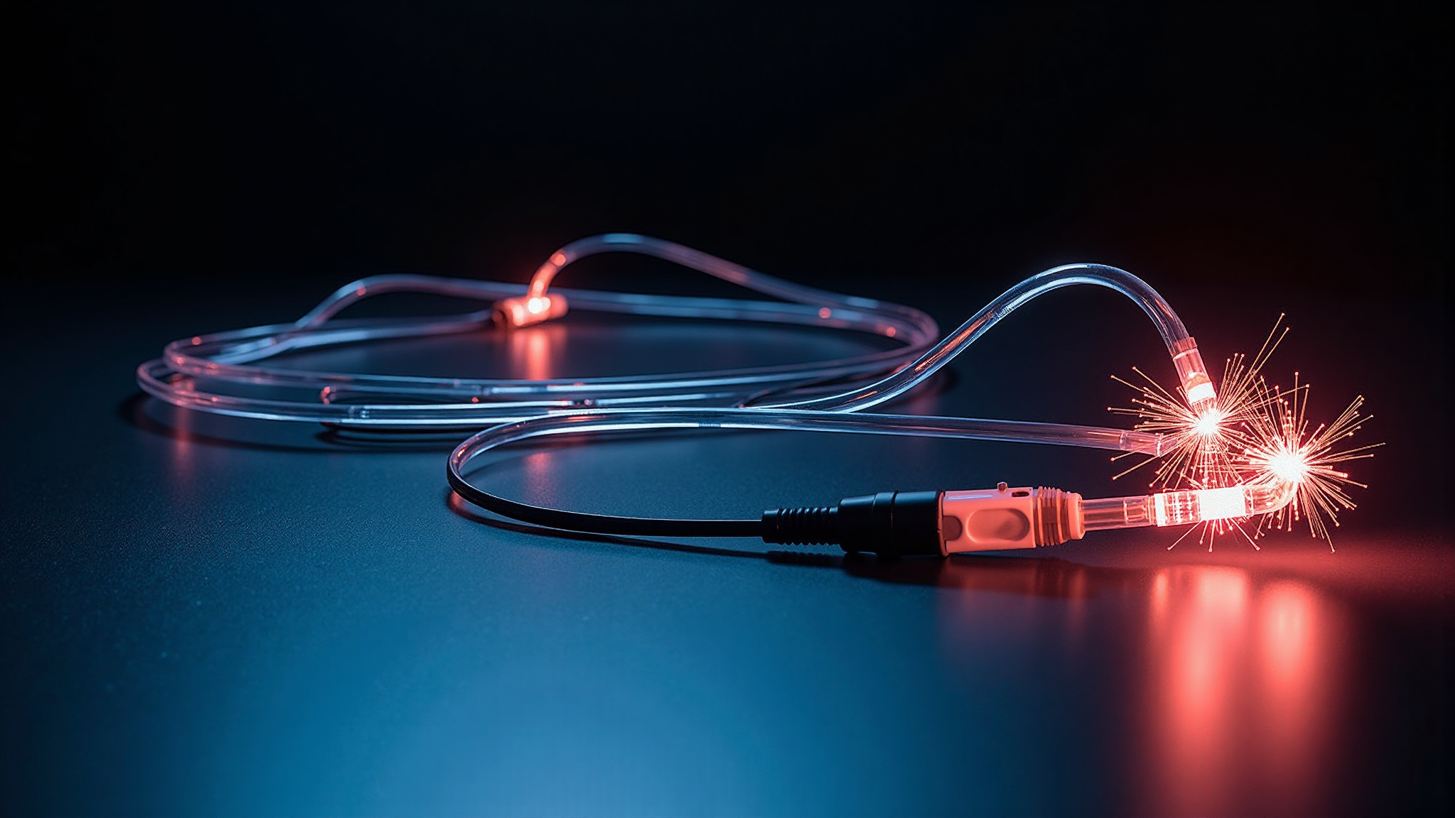
OTDR testing is the cornerstone of fiber characterization. The instrument launches a series of light pulses down the fiber and measures the backscattered and reflected light returning to the source. By analyzing the trace, technicians can identify the location and magnitude of every splice, connector, bend, and break along the link.
Key OTDR Parameters
- Pulse width — Determines resolution versus dynamic range trade-off. Shorter pulses reveal closely spaced events; longer pulses reach farther distances.
- Wavelength — Standard test wavelengths are 1310 nm and 1550 nm for single-mode fiber. Testing at both wavelengths reveals bending losses that only manifest at longer wavelengths.
- Range and averaging time — Set the range to 1.5–2× the fiber length. Longer averaging times reduce noise but increase test duration.
Tip: Always launch the OTDR from both ends of the fiber. A single-direction test can miss loss anomalies caused by mismatched mode field diameters at splices.
Step 2: Insertion Loss Measurement
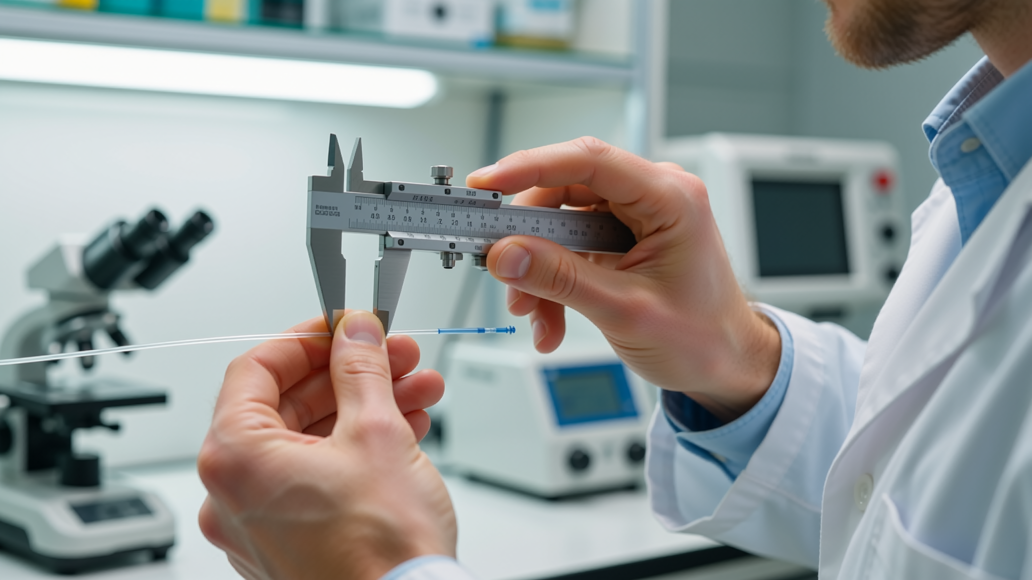
Insertion loss quantifies the total optical power lost between the transmitter and receiver ends of a fiber link. This is the single most important pass/fail criterion for any installation. The measurement is performed using a calibrated light source and power meter (LSPM) set to the operating wavelength of the network.
Measurement Procedure
- Establish a reference power level by connecting the LSPM directly to the light source via a launch cable.
- Record the reference power in dBm.
- Insert the fiber link under test between the launch and receive cables.
- Record the measured power and calculate insertion loss: IL = Reference Power − Measured Power.
The result must fall within the loss budget allocated by the design. Typical thresholds are 0.3 dB per connector and 0.1 dB per fusion splice for single-mode fiber. Multimode connectors generally allow up to 0.5 dB per mating.
Step 3: Return Loss Testing
Return loss measures the amount of light reflected back toward the source at connectors, mechanical splices, and other discontinuities. High reflections degrade laser source stability, increase bit-error rates, and can damage sensitive optical components in high-power systems.
Acceptance Criteria
| Connector Type | Minimum Return Loss |
|---|---|
| UPC (Ultra Physical Contact) | 50 dB |
| APC (Angled Physical Contact) | 60 dB |
| Mechanical splice | 40 dB |
Return loss is measured with a dedicated optical return loss meter (ORLM) or an OTDR equipped with return loss analysis. APC connectors are specified for applications where reflections must be minimized, such as analog video transport and PON networks.
Step 4: Documentation and Reporting
Every test performed must be documented with traceable records that include date, technician name, instrument serial numbers, calibration dates, and environmental conditions. Proper documentation serves multiple purposes: it provides proof of compliance to the customer, creates a baseline for future troubleshooting, and supports warranty claims.
Essential Report Elements
- OTDR traces stored in both image format and Sorbell (.sor) format for re-analysis.
- Insertion loss and return loss values tabulated per link with pass/fail indicators.
- Event tables listing every connector, splice, and reflective event with distance and loss values.
- Photographs of patch panels, cable routing, and labeling for as-built verification.
Tip: Use automated fiber management software to archive test results. When a network issue arises months later, having searchable historical data reduces mean-time-to-repair dramatically.
Conclusion
A disciplined testing regimen—OTDR characterization, insertion loss verification, return loss measurement, and thorough documentation—transforms fiber optic deployment from a hopeful installation into a certified, reliable network. By following these four steps on every project, organizations ensure their optical infrastructure delivers the performance, availability, and longevity that modern applications demand.